Overview
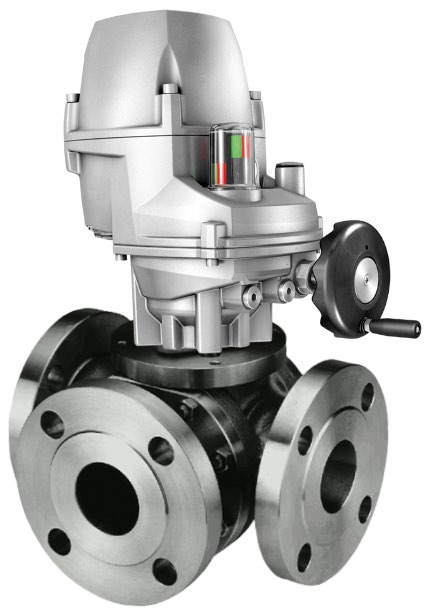
The 3-way control valves consist of a heavy-duty ball valve and either a quarter turn electric or pneumatic actuator. The valves provide a high degree of accuracy and repeatability for accurate temperature control and are equally accurate in mixing or diverting service over a wide flow range. The heavy-duty rotor design provides tight temperature control without high maintenance requirements. The system is available in three standard control configurations: electric; pneumatic; and electro-pneumatic, offering flexibility for most requirements.
Some actuator options are designed and reinforced for vibration service and are qualified to Lloyd’s Marine Requirements for shipboard service. Certain valve and actuator combinations can be directly mounted to reciprocating machinery such as diesel engines, without vibration isolation. Standard valves are suitable for a variety of fluids such as water, water/glycol, sea water, lubricating and hydraulic oils. Optional body materials are available for services involving synthetic or fire-resistant oils, deionized water and ammonia or freon in oil.
For engines, turbines, gearboxes and heat exchangers
- Charge air cooling
- Secondary cooling systems
- Fuel and lube oil preheating
- Co-generation
- Engine jacket water
For refineries, chemical plants and oil reproduction
- Waste heat boilers
- Product coolers
- Product heaters
- Product condensers
Key benefits
- Ease of integration – valve size matches pipe size, resulting in reduced installation time and installation costs
- Flexible design – ports can be configured to suit installation
- Low pressure drop compared to other valve types
- Small physical size
- Hand wheel allows manual adjustment of valve (optional on pneumatic valve)
- Easy installation and maintenance
- Low internal leakage over closed port: Class II (0,5%) ANSI/FCI 70-2 and IEC 60534-4
- Withstands high differential pressure across the closed valve port
Mixing applications
Lubricating oil temperature control is normally configured in a mixing application controlling the return temperature to the heat load. The temperature is normally measured as close as possible to the pump return.
Diverting applications
Jacket water cooling in diverting applications regulates the outlet coolant water temperature from a diesel or gas engine. The valve either sends water to a cooler or bypass loop, accurately maintaining the temperature. The temperature is normally measured at the outlet from the heat source.
Charge air applications
The intercooler is used to cool high temperature turbo charger air. In this application the valve regulates the flow of cooling water through an intercooler, increasing efficiency, enhancing performance and helping to meet today’s environmental requirements.
Specifications
- · Lightweight & compact design
- · Configurable ports = flexibility on installation
- · Low pressure drop = savings on either valve or pump size
- · High accuracy = better temp. control
Valve Specification Overview
- Flow to
- 2 – 500 m³/h
- Sizes
- DN15 – DN150
- Body materials
- Steel; Stainless Steel; Stainless Steel w/ nano polymer
- Temp. range
- Min −40 °C · Max +150 °C
- Max internal valve pressure
- 25 bar
- Seal material
- RPTFE
- Seal compatibility
- Water; Ethylene/Propylene Glycol; Oils – synthetic based; Oils – petroleum based
Applicable Standards
- Design standard
- DIN3357
- Face to face dimension
- Factory standard
- Test standard
- EN12266
- Flange dimensions
- EN1092-1
- Internal leakage
- Class II (0,5 %) ANSI/FCI 70-2 / IEC 60534-4
Property Specification
- Nominal pressure class
- PN16 / PN25
- Air seal test
- 6 bar
- Hydraulic seal test
- 25 bar
- Pressure equipment compliance
- Pressure Accessory – Sound Engineering Practices (SEP)
Comment: In its design as a temperature control valve, the valve is defined as a Pressure Accessory under the terms of the EU Pressure Equipment Directive (PED) and the GB Pressure Equipment (Safety) Regulation (PE(S)R). When used within the temperature and pressure limitations given in this table, the valve range is designed for use in applications using non-hazardous liquids defined as Group 2 in the Directive/Regulation (such as water, water/glycol and lubricating oil). In these applications, the valves fall into the Sound Engineering Practice (SEP) category. Contact us to discuss solutions if the application and/or specifications are outside of the above limitations, or if it is to use hazardous liquids (Group 1) or contain non-hazardous (Group 2) or hazardous (Group 1) gases.
Flow rates
Recommended flow rate in m³/h.
| Size | Inches | Kv | Min m³/h | Ideal m³/h | Max m³/h |
|---|---|---|---|---|---|
| DN65 | 2½" | 128 | 15 | 56 | 70 |
| DN80 | 3" | 146 | 20 | 64 | 80 |
| DN100 | 4" | 456 | 50 | 200 | 250 |
| DN125 | 5" | 730 | 80 | 320 | 400 |
| DN150 | 6" | 913 | 100 | 400 | 500 |
Dimensions
Flange dimensions: DN65 – DN150: EN1092-1
All dimensions in mm.
| Size | L | D | D1 | D2 | b | f | N–Ød | H | h2 | r | R3 |
|---|---|---|---|---|---|---|---|---|---|---|---|
| DN65 | 277 | 185 | 145 | 122 | 18 | 3 | 8–ø18 | 124 | 17 | 9 | 11 |
| DN80 | 302 | 200 | 160 | 138 | 20 | 3 | 8–ø18 | 155 | 23 | 12 | 14 |
| DN100 | 348 | 220 | 180 | 158 | 20 | 3 | 8–ø18 | 178 | 23 | 12 | 14 |
| DN125 | 420 | 250 | 210 | 188 | 22 | 3 | 8–ø18 | 203 | 23 | 18 | 22 |
| DN150 | 510 | 285 | 240 | 212 | 22 | 3 | 8–ø22 | 260 | 37 | 18 | 22 |
Materials
| No. | Part name | Material |
|---|---|---|
| 1 | Bonnet | ASTM A351 CF3M |
| 2 | Gasket | PTFE |
| 3 | Seat liner ring | ASTM A351 CF3M |
| 4 | Seat | RPTFE |
| 5 | Bushing | PTFE |
| 6 | Body | ASTM A351 CF3M |
| 7 | Ball | SS316L |
| 8 | Gasket | PTFE |
| 9 | Bolt | ASTM A193 B8 |
| 10 | Anti-static spring | SS316L |
| 11 | Upper cover plate | SS316L |
| 12 | Packing | PTFE |
| 13 | Gland | SS316L |
| 14 | Bolt | ASTM A193 B8M |
| 15 | Nut | ASTM A193 B8M |
| 16 | Rear cover | ASTM A351 CF3M |
| 17 | Stem | SS316L |
| 18 | Thrust gasket | PTFE |
| 19 | O-ring | VITON |
| 20 | Disc spring | SS316 |
| 21 | Gland flange | SS316L |
Modes of operation
System Types (Electric)
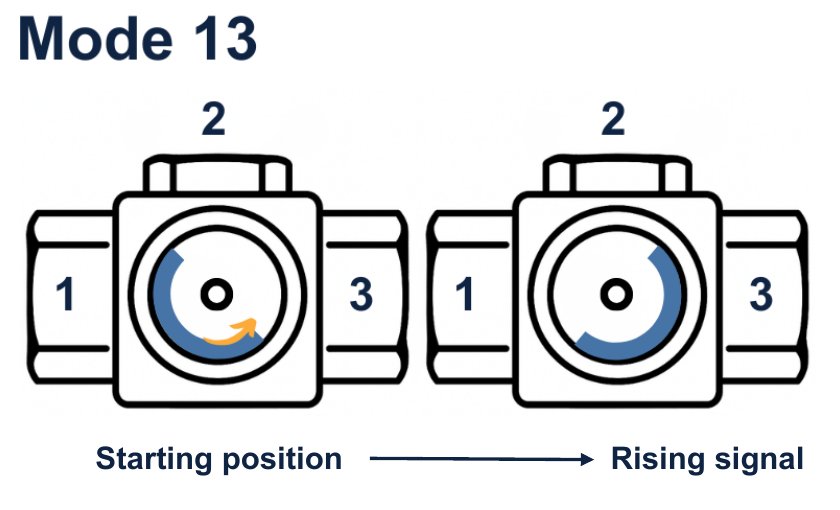
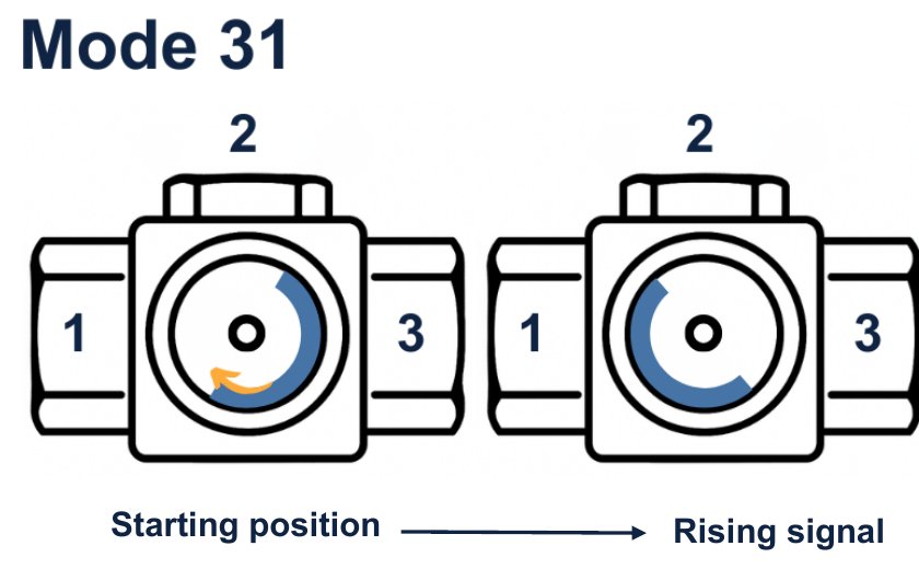
For the electrically operated valves, a number of actuator options are available, which use an electric motor that rotates in either direction in response to the control signals received. The motor drives a gearbox connected to the rotor shaft and turns the valve rotor clockwise or counterclockwise, normally 0 – 90 degrees. At the end of travel, limit switches are incorporated to isolate the electrical supply to the motor when the valve rotor has reached either end of the rotation. A feedback hall sensor is available on some actuators, providing position indication to the control system.
A typical electric valve system incorporates an electrically actuated three-way control valve with an electronic controller and temperature probe. AMOT’s 8071D PID Controller can be either panel or wall mounted. The system is completed with a temperature sensor type 8060.
The electric valve system is simple to install with standard multicore cable and provides more accurate measurement and control than typical pneumatically operated systems.
Model code designation
Valve size
- 65DN65 · 2½"
- 80DN80 · 3"
- 100DN100 · 4"
- 125DN125 · 5"
- 150DN150 · 6"
Flow type
- LLow flow
- SStandard flow
- HHigh flow
Body / seal material
- S216 Steel
- R316 Stainless Steel
- N316 Stainless + Nano polymer
Connection
- BPN10 RF
- CPN16 RF
- DPN25 RF
- UFemale BSPP/G threads
Ball-rotor / leakage class
- SClass I
- HClass II (0.5 %)
- KClass IV (0.01 %)
Mode of operation
- 13Mode 13
- 31Mode 31
- CLConfiguration L
- CTConfiguration T
- MMMulti mode
Actuator
- EAMOT EB
- FAMOT EA
- GAMOT EC
- AAUMA
- HHKC
- VValpes EL
- PPneumatic
Power supply
- 112 VDC
- 224 VDC
- A110 VAC
- B230 VAC
- C400 VAC
Control signal input
- ASwitched live supply
- B4–20 mA
- K0–10 V
- TBUS
Feedback signal
- AEnd position only
- B4–20 mA
- K0–10 V
- TBUS